Comprehensive Infrastructure Inspection System
Dynamic track inspection for data-driven maintenance.
Based on a non-contact track inspection framework, this system employs the inertial reference measurement principle and integrates multiple precision sensors to leverage operational vehicles as carriers, enabling dynamic, real-time monitoring of track geometric parameters and track inspection defects.
Solution
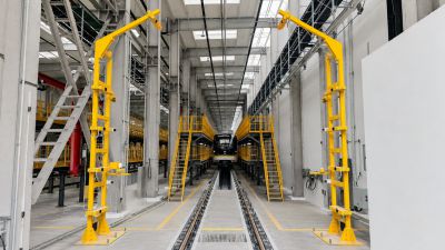
The onboard integrated track inspection system serves as the core component of both intelligent vehicle inspection and intelligent track inspection solutions. Utilizing operational passenger trains as its platform, the system simultaneously performs dynamic monitoring of track geometric parameters (elevation, alignment, levelness, gauge, triangular gap, curvature, etc.) and track inspection defects (rail cracks, missing or fractured fastening components, foreign objects in the ballast bed, broken sleepers, etc.) during normal train operation. The collected inspection data is processed in real time by the onboard intelligent fusion host, which automatically identifies defects and uploads the data to ground-based or cloud-based servers. This system provides critical data support for scientific track maintenance and management, effectively guiding maintenance teams to rapidly locate and rectify track defects, thereby significantly enhancing inspection efficiency and accuracy while reducing labor costs.
Overall Technical Parameters
Technical Specifications Measuring Rangeprecision
Vertical Level Difference of Left and Right Rails(Wavelength: 3 m–25 m) ±60 mm < ±1.0 mm
Vertical Level Difference of Left and Right Rails(Wavelength: 25 m–70 m) ±100 mm < ±2.0 mm
Alignment of Left and Right Rails(Wavelength: 3 m–25 m) ±50 mm < ±1.5 mm
Alignment of Left and Right Rails(Wavelength: 25 m–70 m) ±100 mm < ±3.0 mm
Alignment of Left and Right Rails(Cross Level) ±200 mm < ±1.5 mm
Twist (Triangular Pit)(Base Length ≤ 5.5 m) ±100 mm < ±1.0 mm
Twist (Triangular Pit)(5.5 m < Base Length ≤ 20 m) ±100 mm < ±2.0 mm
Gauge 1415–1480 mm < ±0.8 mm
Curvature ±23° / 30 m ≤ 0.05° / 30 m
Car Body Vertical and Lateral Acceleration -1 ~ 1 g < ±0.01 g
Operating Speed 15–120 km/h < ±0.5 km/h
Inspection Distance 0–9999 km ≤ ±1‰
Rail Vertical Wear 0–15 mm ±0.2 mm
Rail Side Wear 0–22 mm ±0.2 mm
Custom Wear 0–22 mm ±0.2 mm
Full-Section Profile Acquisition Interval < 10 cm
Recognition Rate ≥95%
False Alarm Rate ≤5%
Missed Detection Rate ≤1%
Cracks, Spalling Rail
Misalignment Rail
Missing bolts, nuts and washers; loose nuts Fastening Components
Broken joint bars Fastening Components
Missing or broken gauge blocks Fastening Components
Displaced under-rail rubber pad Fastening Components
Broken, missing or loose clips Fastening Components
Obvious water accumulation, foreign objects Integrated Track Bed / Sleepers
Track bed cracks, spalling Integrated Track Bed / Sleepers
Damaged or missing sealing strips of floating-slab track bed Integrated Track Bed / Sleepers
Drainage ditch contains garbage, silt and other foreign matter Integrated Track Bed / Sleepers
Missing or uplifted various slabs within the track bed area Integrated Track Bed / Sleepers
Sleeper spalling Integrated Track Bed / Sleepers
Sleeper cracks Integrated Track Bed / Sleepers
Gap at the limit position between switch rail and stock rail Turnout
Foreign matter between switch rail and stock rail; foreign matter in the flange groove Turnout
Slide chair detached or displaced due to weld failure Turnout
Missing supports, limiters, and gauge tie plates Turnout
Hidden gap at rail joint Turnout
Loose check-rail bolts and shims Turnout
Oil accumulation on the rail top surface Turnout
Loose lubricator oil outlet plate and sensor Trackside Equipment
Detached gauge tie rod Trackside Equipment
Anti-derail guard rail bolts detached; flange groove width changed Trackside Equipment
Working Principle
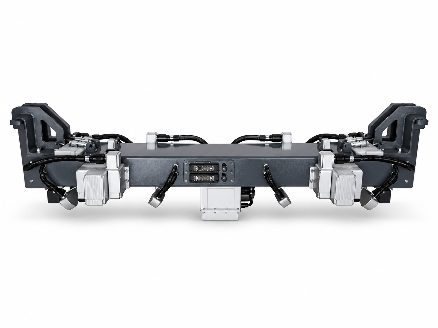
The vehicle-mounted comprehensive track inspection system employs non-contact laser imaging measurement technology and inertial reference measurement principles to achieve dynamic monitoring of track geometric parameters: a laser profile sensor scans the cross-section of the rail, and in conjunction with an inertial package (gyroscope, accelerometer, tilt sensor), it performs two-stage integration calculations to determine rail height, track alignment, levelness, triangular gap, and curvature; track inspection is conducted via a 2D/3D imaging module installed beneath the vehicle, which captures high-definition images; the onboard fusion host then utilizes a CNN-based deep learning algorithm to automatically identify defects such as rail cracks, missing or fractured fasteners, foreign objects in the ballast bed, and broken sleepers; the collected inspection data are then transmitted in real time to a ground-based cloud server through triple positioning—utilizing a speed odometer, RFID electronic tags (placed approximately every 1 km), and sleeper counting (with positioning accuracy ≤1 m).
Why Choose Us
Highly integrated system
The system control software, networking, and power supply are integrated within the core control module, enabling flexible control of the system's operating modes. The system can operate as a complete unit or have any individual subsystem operate independently, thereby meeting the requirements of actual maintenance operations; the hardware employs an integrated design to minimize maintenance interfaces.
Comprehensive positioning is precise and reliable.
By integrating vehicle speed sensor odometry, RFID electronic tags (approximately one per 1 km), and sleeper counting, a triple-positioning approach is employed to achieve a positioning accuracy no greater than 1 m, effectively eliminating cumulative errors caused by wheel slip and serpentine motion.
Vehicle-Infrastructure Collaborative Data Management
The onboard system collects, stores, analyzes, and transmits detection data in real time; defect information is then uploaded to a ground-based cloud server via the vehicle-to-ground communication network, enabling dual data backup and remote real-time monitoring.
Full-scenario intelligent inspection
The system automatically detects various defects in railway tracks, including rail cracks, missing or fractured fasteners, foreign objects in the ballast bed, and broken sleeper sections, achieving a detection rate of ≥95%, a false alarm rate of ≤5%, and a missed detection rate of ≤1%. It also enables high-precision dynamic monitoring of track parameters—such as track irregularity, gauge deviation, triangular depression, and rail wear—with a gauge deviation accuracy of <±0.8 mm and rail wear accuracy of ±0.2 mm.
About Us
Founded in 2018, DITT applies AI visual intelligence to rail transit. Built on our own visual perception algorithms, intelligent hardware and O&M systems, we deliver a full inspection portfolio spanning onboard and wayside applications, now serving 20+ rail transit systems across China.

Together with our subsidiaries — Zhonggang Maintenance, Zhongshu Laser and Yunshang Urban Rail — we are moving rail transit O&M toward predictive maintenance and full-lifecycle management.
0
Company Establishment
0+
Invention Patents
0+
Metro Clients Served
0%+
R&D Proportion of Revenue
Ready to find the right solution?
Our engineers will recommend the best-fit configuration for your specific application — at no cost.
Inquire Now
Related Products
A non-contact dynamic limit detection system, based on a 3D laser profilometer and machine vision, automatically performs external profile acquisition, limit exceedance assessment, and audio-visual alarms when vehicles pass through; this system provides real-time limit safety assurance for the entry and exit operations of rail transit vehicles during maintenance.
Based on a non-contact track inspection framework, this system employs the inertial reference measurement principle and integrates multiple precision sensors to leverage operational vehicles as carriers, enabling dynamic, real-time monitoring of track geometric parameters and track inspection defects.
The integrated obstacle detection system deeply combines sensor data from visible light, infrared, millimeter-wave radar, and LiDAR to enable intrusion obstacle detection and safety early-warning capabilities in rail transit areas. The system is suitable for harsh operating conditions in tunnels and elevated open-air environments; it supports a variety of vehicle types—including metro, intercity rail, tram, and locomotive vehicles—and can also be extended to monitor the status of peripheral equipment and facilities along the main lines.
Latest News
On August 30, 2025, Changzhou Metro Group held the "Changzhou Metro Line 1 EMU Intelligent Inspection System Expert Review Meeting" at the Baizhang Depot.
On September 18, the three-day "2025 China International Urban Rail Transit Exhibition" (MetroTrans 2025) officially opened at the CRCC Qingdao World Expo City.
Frequently Asked Questions
What is the system detection speed?
The detection of track geometric parameters is performed at a detection speed of 120 km/h, and the detection results remain consistent across different speeds; the operational speed detection range spans from 15 to 80 km/h, and all geometric parameters are spatially synchronized with the mileage information.
What level of detection accuracy can be achieved?
Track gauge accuracy: <±0.8 mm; rail vertical and lateral wear: ±0.2 mm; horizontal deviation: <±1.5 mm; distortion (triangular gap): <±1.0 mm (for base lengths ≤5.5 m); positioning accuracy: ≤1 m
What types of orbital defects can be identified?
Capable of detecting rail cracks, chip-outs, or misalignment; missing or loose fastening bolts and nuts; broken spring clips; water accumulation, foreign objects, or cracks in the ballast bed; cracks or chip-outs in sleepers; gaps or foreign objects at the tip rail of switches; as well as oil accumulation on auxiliary equipment, or detachment of guard rail bolts.
What is the accuracy rate of defect detection?
The system recognition rate shall be ≥95%, the false positive rate shall be ≤5%, and the false negative rate shall be ≤1% (tests conducted in accordance with clause 10.3.3 of GB/T 25021-2010).
How to locate detection data
An initial distance estimation is performed using a speed sensor-based odometer, followed by distance correction utilizing RFID electronic tags (approximately one tag per 1 km) and sleeper counting; the positioning accuracy is ≤1 m, effectively eliminating cumulative errors caused by wheel slip and serpentine motion.
How to manage and trace testing data
The onboard integrated host collects, compresses, and stores raw images in real time, while also retaining original defect images; these data are then uploaded via vehicle-to-ground communication to a ground-based cloud server to achieve dual backup; the ground-based platform supports defect traceability, statistical reporting, and trend analysis.
What components make up the system?
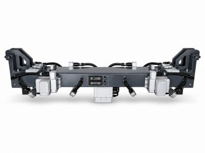
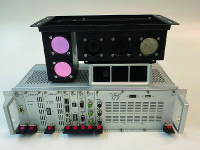
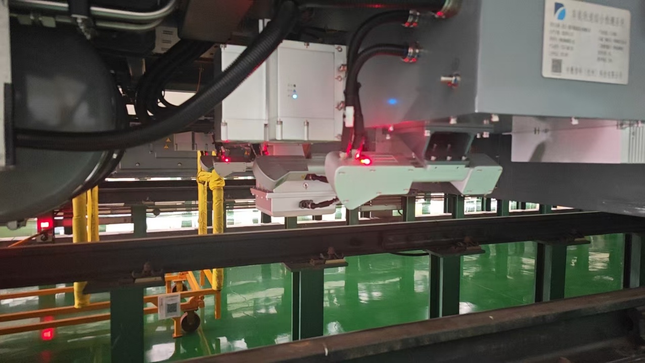
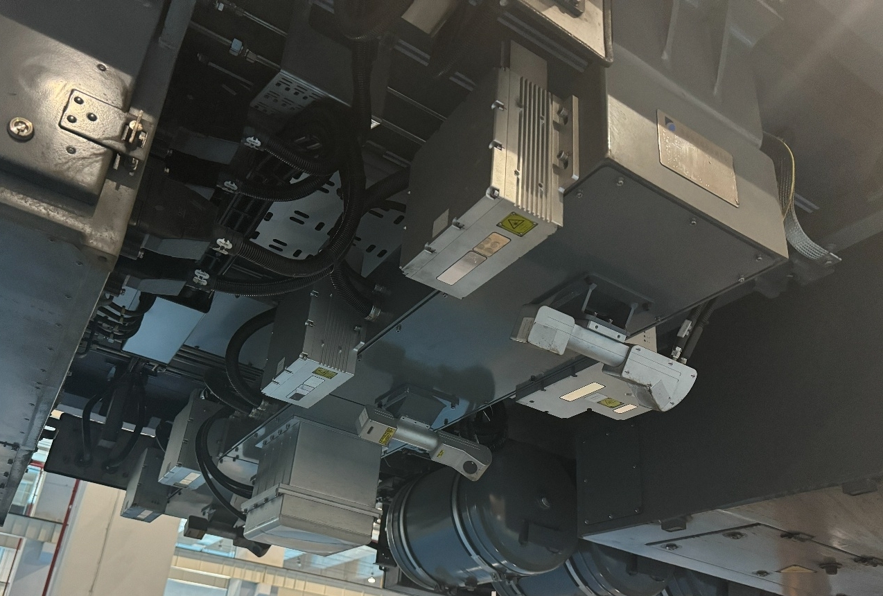
The system consists of three components: in-vehicle equipment (intelligent converged host), under-vehicle integrated inspection beams (including 2D/3D imaging and geometric inspection modules), and a ground-based platform (server and display terminals).
Product Inquiry
Whether you'd like a quotation or simply want to learn more about us, we're happy to hear from you.
202
Phone
WhatsApp
Email
LinkedIn
Facebook